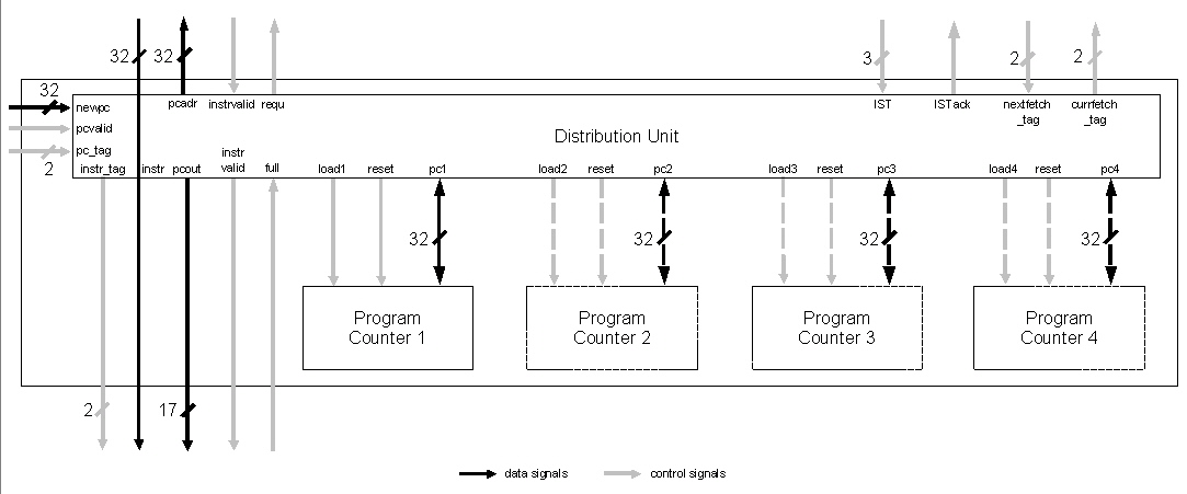
Figure 4.4: Instruction Fetch Unit
If the decode stage recognizes a branch instruction the appertaining branch target address will be computed in the execution stage. This address is given to the fetch stage with a tag for the thread it belongs to, so that the corresponding program counter can be reloaded. If the right next instruction after a branch instruction is not existant in the buffer, the instruction window must be completely reset. Different strategies exist to cope with this problem.
When a branch is taken this first variant of pipeline prototype procedes with execution just like nothing has happened. This strategy is called "always not taken". It is one out of many explained in [16].
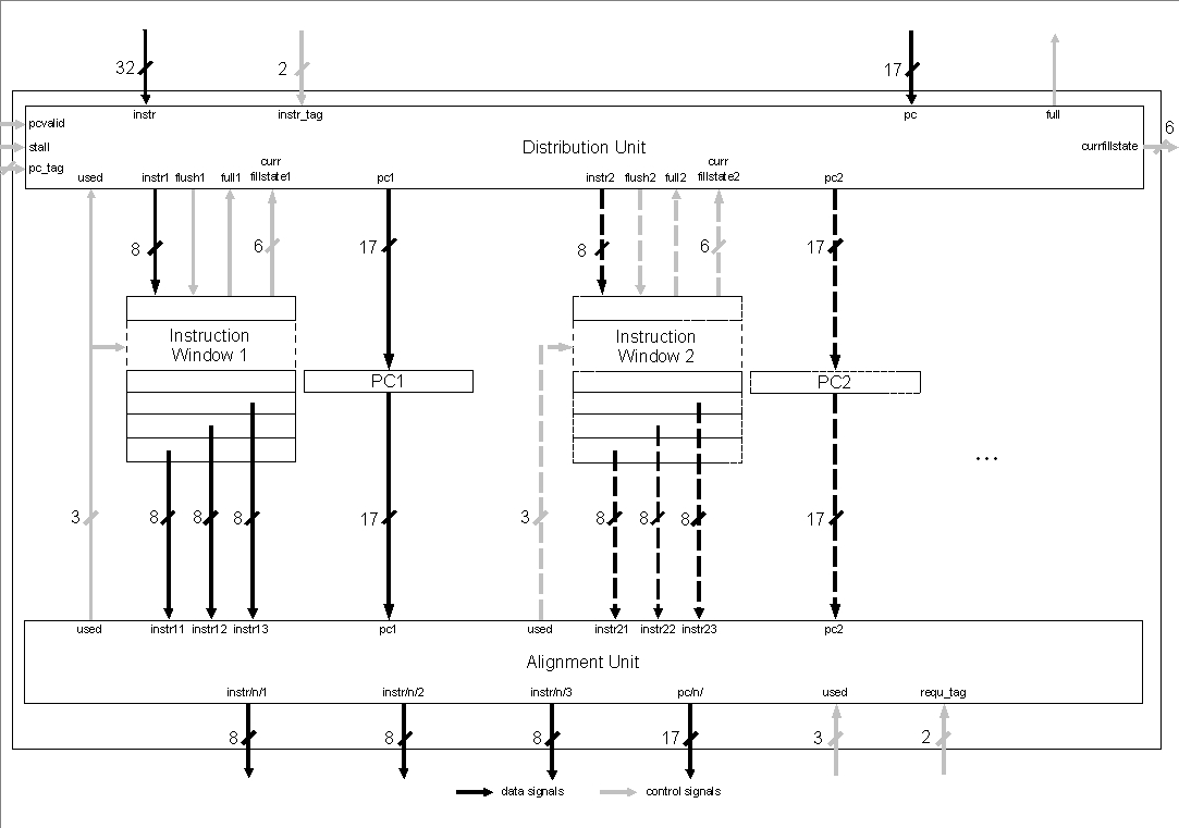
The following instruction window manages storing non-used instruction in a fifo (first in first out) structure and can be seen as the buffer register between the first two pipeline stages. But it is more than that:
There are two memory structures in this Instruction Window Unit (IWU): the shift register for instruction buffering and a program counter buffer. The instruction fifo has 8 entries of 8 Bit width (1 Byte). This size is based on the following consideration: Short Bytecode-instructions are 1 Byte long, long Bytecodes have a length up to 5 Byte. Bytecode analysis shows (Sun Microsystems Inc., [9], [13]) that the average Bytecode instruction has a length of 1.8 Byte. As a result the buffers can hold one instruction at minimum, eight at maximum and about four instructions on an average. Simulations with different buffer sizes and fetch strategies are done in [26].
A problem is the processing of the program counter belonging to the first entry of this fifo buffer. It has to be passed to the following execution stage because branch target address calculation is done there. It cannot be passed directly, because of the split-up of 32 Bit fetch data into 8 Bit fifo data. A new PC has to be computed out of fill-level information from the instruction buffer and the PC for the next memory data.
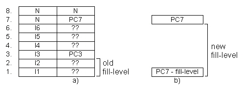
In fig. 4.5 a) one box symbolizes one entry in the buffer. It can be filled by an instruction (I1..n) or not used (N). The program counter buffer on the right holds the belonging program counter (PC1..n) or is not filled. Only every four bytes comes a new program counter, all others are not known (??).
Logic can be reduced by one counter (seen in b)), as the actual program counter can be computed out of fill-level information and the PC for fetching the next instructions. Both possibilities should result in almost the same hardware costs since in variant b) the number of program counter buffers can be reduced to one.
Computation of the new PC for the execution stage becomes easier when incrementing it in the fetch stage by 4 instead of 1. The two least significant bits are only used in the pipeline while the others build the address for external memory access. In figure 4.6 the structure of this buffer can be seen.